
Construction | Mining
The Construction | Mining category contains case studies and blogs related to ITM’s engineering and testing services for the mining and construction industry.
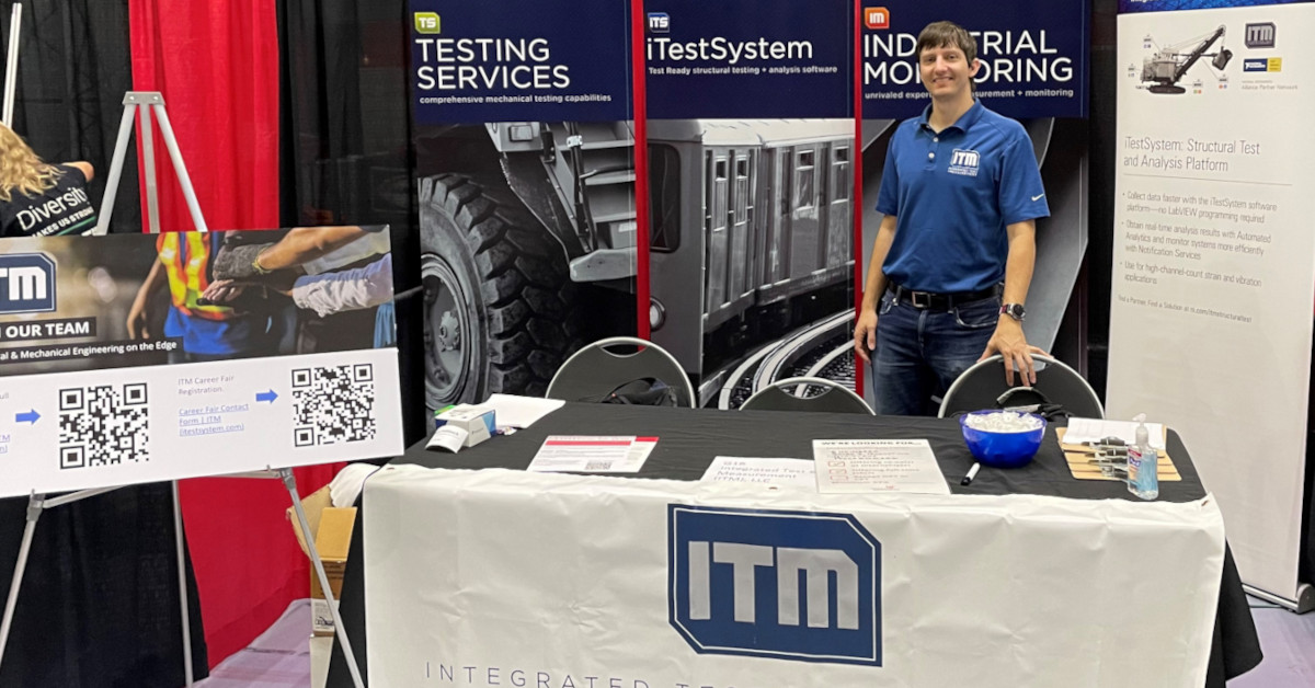
ITM connects with future engineers at UC Career Fair

ITM connects with future engineers at UC Career Fair
Mixed among the buzz of voices inside the massive six-court gymnasium at the University of Cincinnati Technical Career Fair this week, ITM connected with a ton of impressive engineering students.
Potential full-time employees and co-op students heard for the first time about our engineering firm in Milford, Ohio. It is always a joy to watch their eyes light up as we share the projects our team has the opportunity to deploy across the country and around the world.
The aerospace students hear that we work on rockets. The mechanical engineering students learn of the rugged measurements we collect on massive machinery. And the computer programmers discover that we’ve spun up our own software products.
The reaction is almost always the same: “Wow! I had no idea.”
For our team, the day is equally as fulfilling as we connect with the next generation of engineers eager to get to work and apply their knowledge.
Our firm is interested in filling full-time roles for students graduating with a degree in mechanical engineering, mechanical engineering technology, electrical engineering, electrical engineering technology and aerospace engineering.
Are you a current student or recent graduate who loves adventure, travel and has an entrepreneurial spirit? Discover a culture driven by innovation at ITM. Check out our job postings or fill out our co-op questionnaire (/jobs/).
Come Visit our Booth at the UC Career Fair
Looking for a new career? Come visit us at the University of Cincinnati Career Fair!
Where: UC Rec Center, Booth G18
When: Sept. 15th, 2022 – 10AM – 2 PM
For more information about available jobs, contact Josh Fishback via email: josh.fishback@itestsystem.com or phone: (844) 837-8797.
Modern Tools Series: What’s In The Box?
Modern Tools Series: What’s In The Box?
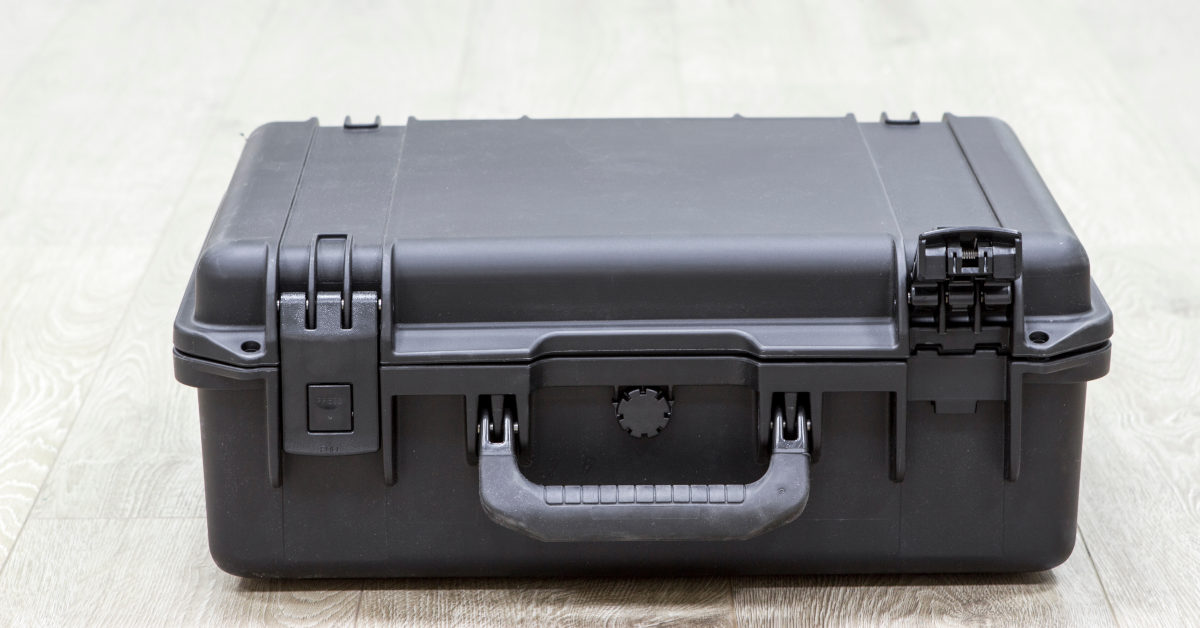
This box reveal may not be quite as dramatic as the ending of “Seven,” the ’95 serial killer thriller that blew moviegoers’ minds, but the ITM team is throwing open the latches nonetheless.
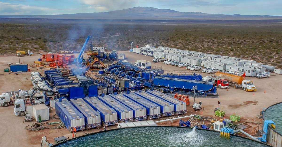
In this case, our team is taking you on a quick tour of a recently deployed Rugged Data Acquisition System. These particular black boxes of tech are riding around on high-dollar fracking equipment to remotely monitor all sorts of triggering events. Our crew builds them on the regular, and the end result is that our clients can better understand what sorts of stress, strain and vibration is taking place both en-route to their site and once operations begin.
ITM is known for building rugged measurement systems and data logging solutions that are deployed on everything from Class A trucks, to well frac trailers, to dam and bridge structures, oil pipelines, gensets, boilers and more.
So, without further ado, what’s in the box?
We recommend a handful of essential components and elements if you are looking to build your own rugged measurement system:
- An Industrial Embedded PC. We love the Nuvo-7000LP. Another favorite is the Advantech UNO-2484G-9S55.
- You’ll need industrial grade connectivity, and you can’t beat Peplink’s cellular router options. And remember to outfit that unit with an AT&T or Verizon plan and get that activated card installed.
- A remote desktop application is a must, and we usually turn to LogMeIn for our remote access and file management. This allows us to pull up any of our units no matter where they are in the world to check in on status or grab some data for our clients.
- Speaking of data, depending on your job, you’ll likely need lots of data storage capability. Our preference is a 2 terabyte USB drive, which gives us an almost unlimited amount of space. If needed, we can store about six months worth of data before hitting capacity.
- Since our industrial PC is running Windows, we use iTestSystem, our proprietary engineering measurement software platform that enables test engineers to organize, acquire, view, and analyze data from machinery, processes, vehicles and other complex systems.
- To complete the box, our industrial PC is connected to an NI c-DAQ outfitted with strain, vibration and voltage modules.
- What about power you ask? In our fracking instance, we connected to an alternator which charges a bank of batteries in the RAC.
So there you have it. That’s what’s in the box. Build your own, or get in touch with our team, and we’ll customize a system for your specific needs.
We also install and service all of our equipment. So if something breaks in the field, we can get you back up and collecting data or even assist with data analysis.
For more information about our rugged data acquisition systems, on-site system deployment or data analysis services, contact Josh Fishback via email at josh.fishback@itestsystem.com or phone at (844) 837-8797 x705.
Endless Testing Options Through Finite Element Analysis (FEA)
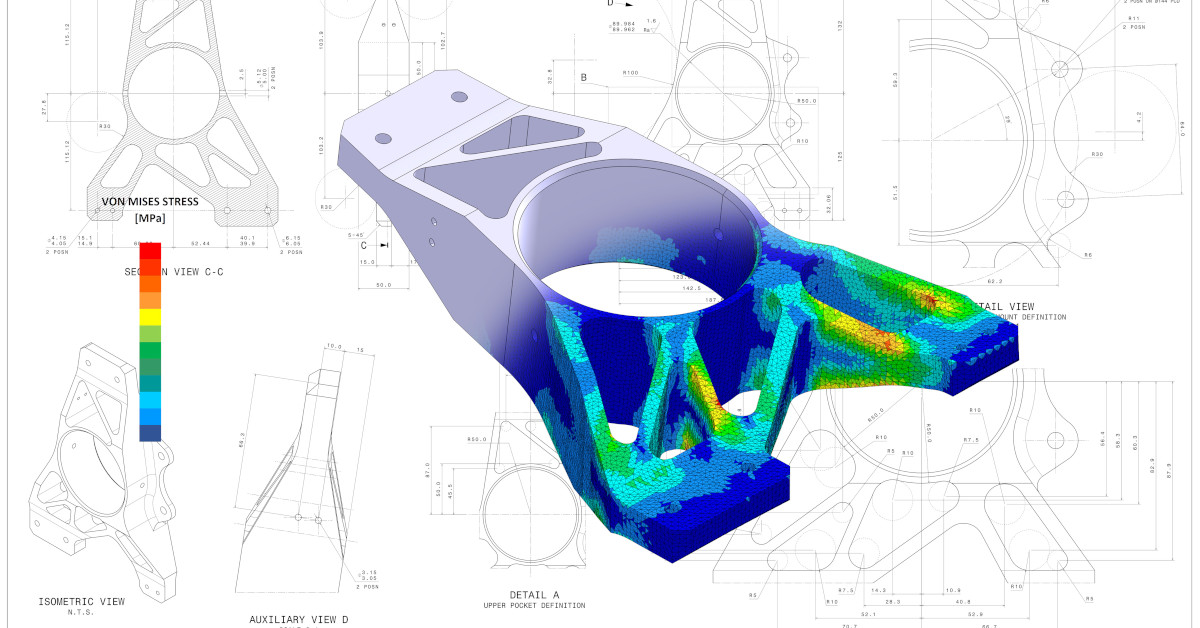
Design Validation Finite Element Analysis (FEA) using strain gauge measurements.
Endless Testing Options Through Finite Element Analysis (FEA)
Whether our customers need us to validate their Finite Element Analysis (FEA) models or perform both the physical testing and the FEA, our engineers are used to helping customers with complex testing and analysis of high-value equipment.
As a recent example, our team is involved in a large-scale project to do engine testing for a client that requires ITM to do both the physical testing as well as the FEA simulations. This requires using a custom high-channel count telemetry system to transmit engine data to a receiver that is sampling at an extremely high rate.
“Once you are able to bring in the test data and compare it to the simulated data, you are able to fine tune your FEA simulation to better reflect the real-world application,” said ITM engineer Ryan Matthews. “We can also simulate the test in software and predict how it is going to react to the test when we can actually measure such things as strain, stress and vibration.”
Matthews points out that FEA technology also helps the team determine the precise best placement of strain gauge during physical testing. And depending on complexity, a single simulation can take a few seconds or months to run.
For obvious reasons — mainly the cost of bringing high-value assets to failure — running repeated strain gauge tests on components simply isn’t feasible, but ITM’s in-house capabilities and close partnership with sister firm SixDOF opens up endless FEA simulation options to clients.
“Sometimes you are only going to be able to test a structure or a part once before it fails,” says Matthews. “So it becomes crucial to do a limited number of physical tests then correlate that to your FEA. Then you can pretty much run unlimited simulations.”
For more information about our testing, strain gauging, and FEA modeling services contact Ryan Welker via email at ryan.welker@itestsystem.com of phone @ (844) 837-8797.
In Vehicle Vibration Testing
building a rugged and flexible in-vehicle testing solution to measure the vibration levels.
Vehicle Component Testing
…more than a thousand miles away. A display of gauges, needles and dials showed precisely how their product performed during every day over-the-road stress.
Collect Vehicle CAN Bus data with NI 9862 and iTestSystem
Automotive and off-highway engineers and designers often need to log vehicle bus data along with vibration, strain gauge, and other sensor data during normal operation to evaluate their design. Using data from all these sources enables these engineers and designers to pinpoint a vehicle’s response to staged or damaging events. For example, engineers can see how steering wheel position and speed effect structural response when the vehicle hits a pothole.
How does steering wheel position and speed effect structural response when the vehicle hits a pothole?
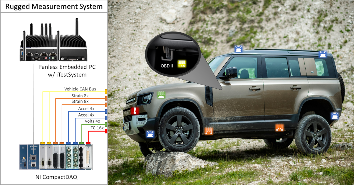
In situations where our engineers need to tap into the vehicle’s on-board diagnostics using CAN bus data and analog sensor data to identify and solve a problem, we will deploy a rugged measurement solution based on NI CompactDAQ (cDAQ) hardware. These systems usually include an industrial compact pc or standalone cDAQ running the iTestSystem engineering measurement application. iTestSystem logs data from the vehicle bus connected to NI 9862 CAN module and other analog sensors connected to NI cDAQ modules like NI 9234, NI 9236, and NI 9229 into one data file.
NI 9862 CAN Module Specifications and Connections
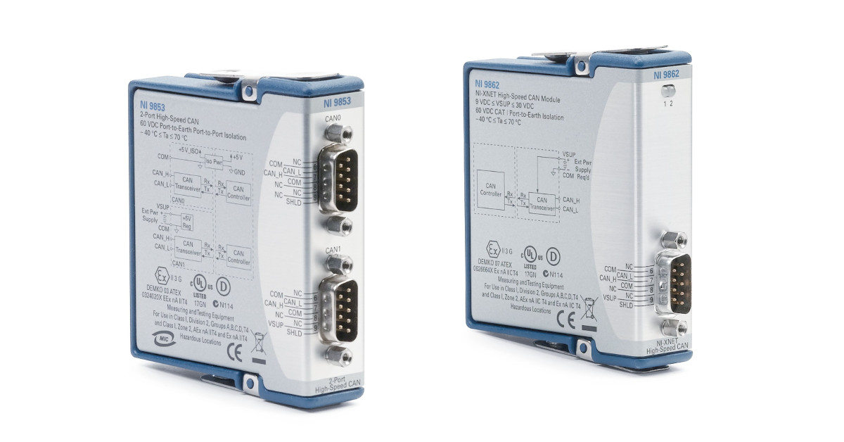
According to the NI data sheet, the NI 9862 modules is a single CAN port device that is isolated from the other modules in the system. The port has a Bosch DCAN CAN controller that is CAN 2.0B-compatible and fully supports both 11-bit and 29-bit identifiers. The port also has an NXP TJA1041AT High-Speed CAN transceiver that is fully compatible with the ISO 11898 standard and supports baud rates up to 1 Mbps. This module requires +9 to +30 VDC supply voltage to operate.
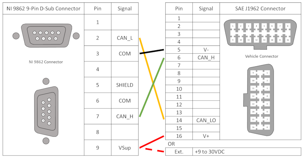
The table below shows the connections between the NI 9862 9 pin D-Sub and the SAE J1962 connector that are required for CAN communication. NI sells a OBDII9M-DB9F CAN Cable cable if you don’t want make your own cable.
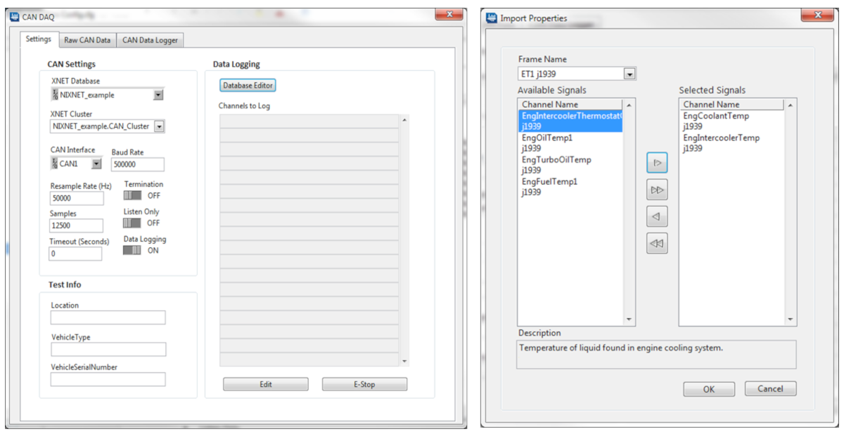
iTestSystem CAN Channel Setup
Setting up a vehicle CAN bus connection can be difficult, especially if you need to acquire non-standard, proprietary messages and frames. iTestSystem simplifies this setup by leveraging the NI XNET and CAN drivers to view and configure CAN bus data, import databases, and assign scale factors. iTestSystem then allows users to browse and choose which CAN signals to acquire.
For more information about collecting CAN bus data with an NI 9862 and iTestSystem, or our testing services, contact Chase Petzinger via email at chase.petzinger@itestsystem.com or phone at (844) 837-8797 x704
Related Links
ITM Gathers Dam Spillway Data During Midair Strain Gauge Project

Suspended in a harness 30 feet above a concrete spillway in central North Dakota, ITM engineer Ryan “RJ” Matthews instruments the gate of one of the world’s largest earthen dams with dozens of strain gauge sensors.
Integrated Test & Measurement’s field service technicians and engineers have installed strain gauges on civil structures and machinery around the globe for decades, and this project represents one more example of rugged data acquisition. In this instance, the team rappelled from an overhead abutment on the Garrison Dam — a 2-mile-long structure along the Missouri River built by the Army Corp. of Engineers starting in 1947.
Contracted by Cotech IRM Services, ITM was charged with collecting data to measure the strain on one of the 28 spillway gates which are designed to raise and close to allow water to pass from the reservoir during rare flood events. Just behind those gates is Lake Sakakawea, one of the largest man-made lakes in the United States.

Despite the complex location, Matthews and co-worker Zach Strong were able to successfully instrument the spillway gate with 44 single-axis strain gauges and solder signal cables which lead back to a NI CompactDAQ system connected to their laptop, allowing them to successfully gather streams of crucial data using iTestSystem while the gate was put through its paces.
The project is yet another example of ITM’s ability to combine the use of strain gauge sensors, a cDAQ system and the firm’s iTestSystem software to create a structural health monitoring system. In this instance, the project required only one-time testing, but ITM can also establish a permanent structural health monitoring system as well. iTestSystem is an engineering measurement software platform that enables test engineers to organize, acquire, view, and analyze data from machinery, processes, vehicles and other complex systems. iTestSystem was specifically designed for use with National Instruments (NI) cDAQ hardware for data collection and data logging.
For Matthews, it was his first experience installing strain gauges while strapped into a bosun’s chair and dangling in midair, but he points out that ITM’s strain gauge process is essentially the same whether their engineers are standing on a bridge or inside a railcar. All that changes is the method of access and environment.
His field notes reveal that each strain gauge on this job was wired in a quarter bridge configuration, which provides one individual measurement of strain (positive tension or negative compression) per location. All gauges were adhered to the gate using M-bond 200 epoxy. A final report submitted to the customer contained detailed instrumentation and test notes and results reported in a series of stress/strain tables and stress graphs.
Contact ITM for your Strain Gauge Needs
Installing strain gauges in the field for structural and fatigue measurements requires expertise and experience. Whether you use our iTestSystem software to stream and analyze strain signals for static measurements and real-world fatigue data acquisition or contract our software engineers to build a real time strain monitoring system, we will make sure you acquire quality strain data. Contact our strain lab and technicians to install strain gauges on test specimens or to design, build, calibrate, and test strain-based load cells.
Strain Lab Contact Info: Ryan.Welker@iTestSystem.com, (844) 837-8797

ITM provides software development, structural and mechanical testing services, industrial monitoring, strain gauging, and data analysis solutions to clients on six continents. ITM is a recognized National Instruments Gold Alliance Partner.
![]()